


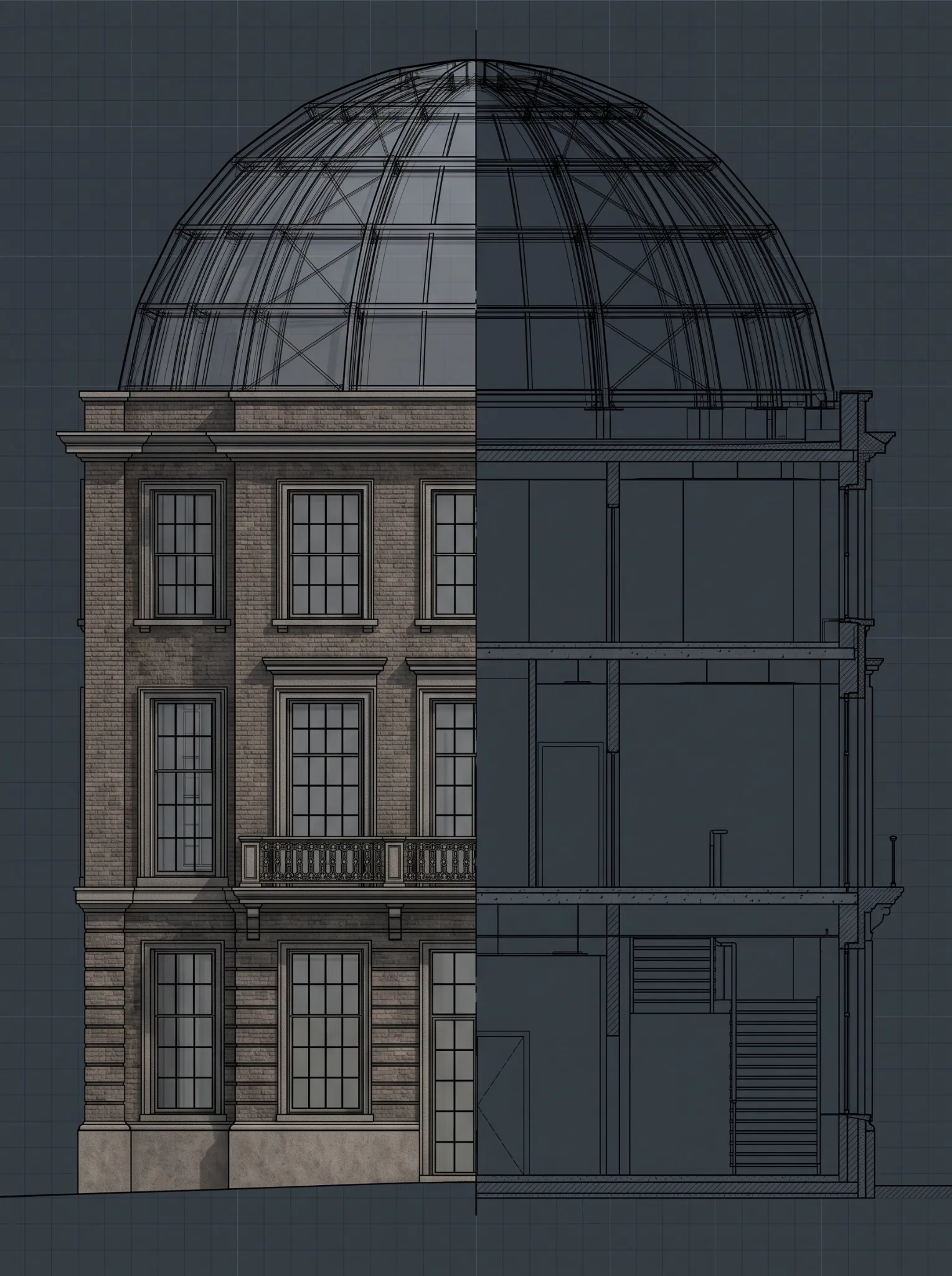
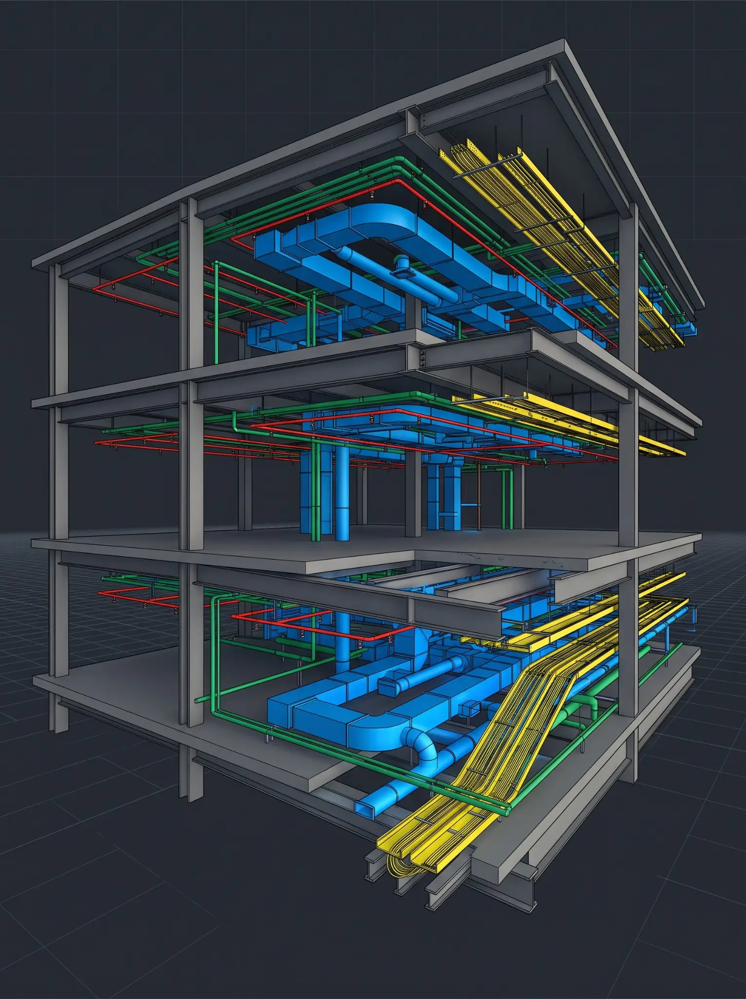
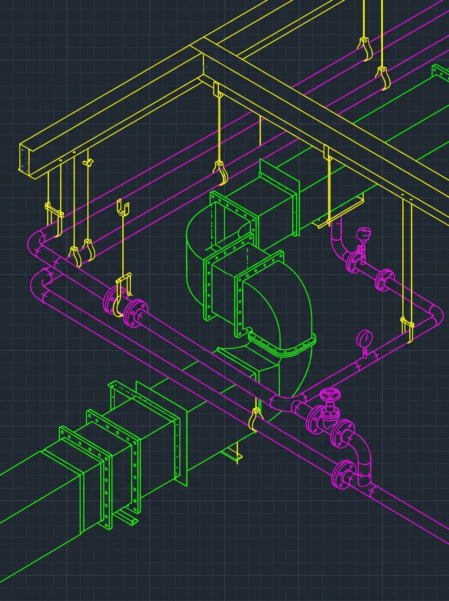








Choosing between Revit and Tekla is rarely just a software decision. For steel fabricators, MEPF contractors, detailers, and general contractors, it determines how design information becomes coordination models, fabrication details, shop drawings, material data, and controlled field releases.
Both platforms have a place in BIM delivery, but at different points:
- Revit is commonly used to develop and coordinate multidisciplinary building information across architectural, structural, and MEPF teams.
- Tekla Structures is commonly used where steel detailing, assemblies, connections, and fabrication information need trade-level precision.
The expensive mistake isn’t picking the wrong platform. It’s picking a workflow before defining the required output, model ownership, detailing responsibility, review authority, exchange process, and release controls.
A coordination model can be fine for spatial planning and wrong for shop production. A detailed fabrication model can be rich in component data and still need checking, approval, and field verification before release. So the right workflow starts with one question:
What must this model and drawing package enable the shop or field team to do?
Quick Answer: Revit, Tekla, or Both?
- Use a Revit-led workflow when the priority is multidisciplinary coordination, Revit-native model exchange, documentation consistency, and active design change.
- Use a Tekla-led workflow when the priority is detailed structural steel assemblies, connections, fabrication information, and production drawings.
- Use a connected workflow when the project needs both, with clear rules for model ownership, data exchange, revisions, and release authority.
See the details before you commit the package.Send a construction set or model and get a sample steel or MEPF shop drawing, detailed to your standards.
See a Sample Steel or MEPF Shop Drawing Package →The Workflow Test: What Must the Next Team Do?
Start with the downstream user of the information, not the software.
| Downstream user | What they typically need | Workflow emphasis |
|---|---|---|
| Architect, engineer, or design team | Coordinated design information, schedules, drawings, controlled revisions | Revit-centered design authoring and coordination |
| GC or VDC team | Federated models, issue ownership, coordination views, current status | Controlled model exchange and coordination |
| Steel detailer or fabricator | Members, assemblies, connections, piece information, drawings, material data | Tekla-led or other steel detailing workflow |
| MEPF fabrication team | Spools, assemblies, dimensions, elevations, hangers where included | Trade-specific fabrication workflow linked to coordination |
| Field team | Approved release drawings, current revisions, field-verification notes | Drawing-release and revision control |
| Owner or facilities team | Record, asset, and closeout information | Defined handover and validation process |
Software doesn’t define the output. The project scope, trade responsibility, and approval process do.
Route 1: When Revit Should Lead
A Revit-led workflow usually fits when the main need is multidisciplinary coordination and consistent design documents. That’s common when:
- The architect, engineer, owner, or GC requires Revit-native model exchange
- Architectural, structural, and MEPF teams work in linked design models
- The project is still in design development, construction documents, or active change
- The team needs shared coordinates, linking, schedules, sheets, and documentation consistency
- Trade detail hasn’t yet reached fabrication level
What Revit Does Well Here
- Keeps architectural, structural, and MEPF information aligned
- Manages change across multiple disciplines
- Ties schedules and documentation to model content
- Supports design and constructability review
- Creates trade-ready reference information before detailed fabrication begins
Where Revit Alone May Not Be Enough
When the fabricator needs highly detailed steel assemblies, connection detail, piece information, or shop-specific material data, the work usually needs to move into a dedicated steel detailing environment or a connected production process.
Route 2: When Tekla Should Lead
A Tekla-led workflow usually fits when detailed steel fabrication information is central to the package. That includes:
- Detailed members and assemblies
- Connection components, plates, bolts, welds, copes, and cuts
- Assembly, single-part, and erection drawings
- Bills of materials
- Production outputs where the shop workflow supports them
- Fabricator-managed revision and release control
Tekla isn’t the only option. Many U.S. fabricators detail in SDS2, and Autodesk offers Advance Steel. The same controls apply whichever detailing platform the shop uses.
Software Output Is Not Fabrication Control
Detailed output doesn’t replace fabrication controls. For AISC-certified fabricators, AISC 207-25 requires a documented procedure for checking fabrication and erection documents, with records that identify the individual checker who performed the final check. The check must verify:
- Geometry
- Connections as specified in the contract documents
- Required notes
- Material usage
- Complete shop bills
- Welding symbols
- Coatings and surface preparation
AISC defines checking as a detailed review by a checker other than the original detailer.
The standard also addresses subcontracted detailing directly. When detailing is performed by a subcontractor, the fabricator’s procedure must define how much review is required of the documents it receives before submittal for approval. If an external team details your steel, its output feeds your certification process, and your checking procedure has to account for it.
When Tekla Isn’t the Answer by Itself
Don’t choose Tekla simply because the project has steel. A Tekla workflow still needs:
- Clear structural and connection design responsibility
- Approved, current source information
- Model-exchange and detailing standards
- An independent checking process and named release authority
- Revision control and field-installation coordination
The platform doesn’t determine professional responsibility or approval authority.
Route 3: When MEPF Fabrication Needs Its Own Path
MEPF fabrication is a different problem from steel detailing. The project may need a coordination model for routing and issue resolution, then a separate fabrication package for spools, assemblies, installation, and material planning.
Define whether the scope includes:
- Detailed duct, pipe, cable tray, conduit, or fire protection
- Equipment connections, spools, or assemblies
- Hangers, supports, sleeves, and penetrations
- Elevations, dimensions, and installation references
- Material and component schedules
- Field-verification requirements
- Shop drawings and revision-controlled release packages
The Tools MEPF Fabricators Actually Use
Tekla is not normally the primary MEPF fabrication route. MEPF detailing usually runs through tools like these:
- Revit fabrication parts. Revit can use LOD 400 content from the Autodesk Fabrication products (CADmep, ESTmep, and CAMduct), either to model with fabrication parts directly or to convert a design-intent model to fabrication intent.
- Autodesk Fabrication CADmep. Used by many MEPF fabricators for detailed spooling and fabrication documentation.
- Trimble SysQue. A Revit add-in for LOD 400 MEPF detailing with manufacturer-specific content.
The best choice is the one that connects to the trade’s actual shop and field process without losing control of project information. A coordinated model is not automatically a fabrication model. The project must define the required level of detail, trade responsibilities, fabrication standards, review process and approval path.
Route 4: When Revit and Tekla Work Together
Many projects don’t need a Revit vs. Tekla decision. They need a Revit-to-Tekla workflow. That’s common when:
- Design and multidisciplinary coordination happen in Revit
- Steel detailing and fabrication information are developed in Tekla
- The GC needs a federated coordination environment
- Design changes continue after steel detailing begins
How the Exchange Usually Works
Trimble’s Tekla support documentation lists IFC export as the route for 3D model coordination between Tekla Structures and Revit, Navisworks, or Autodesk’s cloud platforms. It describes creating native Revit files from Tekla as an extremely rare workflow that produces geometry-only files. In practice, most coordination runs on IFC.
Trimble Connect gives Tekla users a shared environment for exchanging model information.
Whichever method you use, agree on four things before the first exchange:
- Coordinates
- Object mapping
- Exchange frequency
- Who re-imports updates
Define the Source of Truth for Each Purpose
Using two platforms isn’t the risk. The risk is two models that both act as uncontrolled sources of truth. Map responsibility before the first exchange.
| Information purpose | Typical source of truth | Key control |
|---|---|---|
| Architectural design intent | Architectural authoring model | Published revision and approval status |
| Structural design intent | Structural design model | Engineer-approved design information |
| Steel detailing and fabrication | Fabricator-controlled detail model | Independent checking, drawing review, fabrication release |
| MEPF trade coordination | Trade models and federated model | Issue ownership and decision log |
| Shop drawing package | Controlled release drawing set | Named checker, release authority, and revision register |
| Field installation package | Latest approved issue for installation | Field-verification notes and superseded-sheet control |
| Handover package | Defined closeout files and records | Project-specific acceptance criteria |
Map your Revit-to-Tekla workflow before the first package moves.In a Discovery Session, we review your source models, trade responsibilities, exchange method, and checking process, and flag where design changes could slip past detailing.
Map Your Revit-to-Tekla Release Workflow in a Discovery Session →The Release Control That Matters Most
The software decision matters less than the release decision.
Consider a common pattern (an illustrative example, not a specific project). The engineer revises a beam size in the Revit structural model to carry the load of a new rooftop unit. The change is published, but the next IFC exchange to the Tekla detail model isn’t due until the following week. Meanwhile, the connection for that beam is detailed, checked against the old size, and released. The mismatch surfaces when the erector can’t make the connection fit. Every tool worked as designed. The release gate never asked which source revision the package was built from.
Before any drawing or model package is released for fabrication, confirm:
- The correct source model and revision are identified
- Applicable RFIs, ASIs, addenda, and approved changes are incorporated
- Design, engineering, connection, and trade-detail responsibilities are clear
- Coordination issues affecting the package are resolved, accepted, or documented
- Required dimensions, elevations, connections, clearances, and access are present
- Drawing-to-model consistency has been checked
- An independent checker has completed and recorded the final check
- The release authority is named
- Superseded files and sheets are controlled
- Field-verification conditions are visible
This is where many workflows fail. A detailed model gets treated as approved production information before anyone confirms it’s current, checked, and released for the intended purpose.
The Workflow-Selection Matrix
| Question | Revit-led | Tekla-led | Connected |
|---|---|---|---|
| Is multidisciplinary design coordination the immediate priority? | Strong fit | Input only | Strong fit |
| Is detailed steel fabrication information the priority? | Depends on scope | Strong fit | Strong fit |
| Does the project require Revit-native exchange? | Strong fit | Needs controlled IFC exchange | Strong fit |
| Does the shop need assemblies, connections, and material data? | May need downstream detailing | Strong fit | Strong fit |
| Are active design changes likely? | Strong fit | Needs disciplined update control | Strong fit with clear exchange rules |
| Does the MEPF trade need fabrication outputs? | Strong fit with fabrication parts or SysQue | Not the primary route | Often right with trade tools |
| Are there multiple model owners? | Needs a responsibility matrix | Needs a responsibility matrix | Needs strict source-of-truth rules |
| Is the workload recurring across projects? | Suits a Revit production team | Suits a dedicated detailing team | Suits a standardized workflow |
Where Excelize Fits in a Revit and Tekla Workflow
Since 2004, Excelize has delivered more than 2,500 BIM projects for more than 300 clients, with primary U.S. project experience in Texas, Florida, New York, New Jersey, California, and Pennsylvania. U.S. offices in New Jersey and California give fabricators and trade contractors an onshore point of contact through submittal and release cycles, and the BIM delivery studio in India provides the production capacity behind it.
Excelize details shop drawings in Revit, Tekla and AutoCAD, with Navisworks for coordination, and doesn’t require a specific platform. For subcontractors and fabricators, that includes:
- Steel and miscellaneous metals: connection detailing and miscellaneous metals modeled in Tekla to your engineer’s connection design. Connection design and engineering stay with your engineer of record.
- MEPF trades: shop drawings, sheet metal and duct fabrication drawings, pipe spool drawings, and 2D coordination drawings coordinated to the construction model.
- Quality and release: drawings checked against the model and your standards before issue, delivered with a window for revisions.
Excelize works natively in Revit and Tekla. For projects using Autodesk Fabrication or Trimble SysQue content, tool compatibility is confirmed during scoping. Detailing scope and checking deliverables are also agreed during scoping, so they fit your own AISC checking procedure.
For a defined package, a per-project engagement fits best. For recurring detailing work with stable templates and standards, a Dedicated BIM Studio keeps knowledge and quality consistent. See Excelize engagement models for both.
Excelize works within the agreed scope. The engineer of record, fabricator, contractor, and designated approver retain responsibility for design, connection design, delegated design, fabrication, field verification, means and methods, and release authority unless assigned otherwise in writing.
FAQ: Revit vs. Tekla for Detailing
Is Tekla Better Than Revit for Steel Detailing?
Tekla is often the better fit when the output includes detailed assemblies, connections, piece details, fabrication drawings and material data. Revit supports structural modeling, documentation, and coordination. The right choice depends on required deliverables, shop systems, project standards, and assigned responsibilities.
Can Revit Be Used for MEPF Fabrication?
Yes. Revit can use LOD 400 content from the Autodesk Fabrication products through fabrication parts, and add-ins such as Trimble SysQue support manufacturer-specific MEPF detailing. A coordination model shouldn’t be treated as fabrication-ready until the required information and release controls are confirmed.
How Do Revit and Tekla Exchange Models?
Trimble’s support documentation lists IFC export as the route for 3D model coordination between Tekla Structures and Revit, and describes native Revit file creation from Tekla as extremely rare and geometry-only. Trimble Connect provides a shared environment for model information. Agree on coordinates, object mapping, exchange frequency, and update responsibility before the first exchange.
What Does AISC Require for Checking Shop Drawings?
AISC 207-25 requires certified fabricators to maintain a documented procedure for checking fabrication and erection documents, performed by a checker other than the original detailer and recorded by name. When detailing is subcontracted, the fabricator’s procedure must define the review required before submittal.
Who Approves Steel Shop Drawings?
Approval depends on the contract, delegated-design requirements, the engineer of record’s role, fabricator obligations, and the submittal process. The software doesn’t determine approval authority. Define it in the responsibility matrix and contract documents.
Choose the Release Path, Not Just the Platform
The Revit vs. Tekla decision isn’t a choice between a good platform and a bad one. It’s a decision about how information moves from design and coordination into detailing, shop drawings, fabrication, and installation:
- Use Revit when multidisciplinary coordination and Revit-native documentation dominate.
- Use Tekla when detailed structural steel fabrication information dominates.
- Use a connected workflow when you need both.
With a connected workflow, define ownership, exchange controls, checking, revision status, and release conditions before the first package moves to production.
Ready to detail your next steel or MEPF package with controlled release?Share your models, drawing set, and release schedule. We’ll quote detailing, shop drawings, and QA/QC scoped to your trade and platform.
Request a Quote for Steel and MEPF Detailing Services →